Wheels, loads and drivetrain
Implementation snapshot · 2026-10-12 · Sources & update notes
Visible wheel CAD and native tire physics are separate. A detailed tire mesh does not supply pressure, friction, carcass stiffness or compound behaviour.
Suspension support loads
Section titled “Suspension support loads”The static solver balances assembled mass and COM over the four contact points, choosing the admissible distribution nearest equal corner loads. Perturbing the linkage measures how moving masses change height with hub travel. That supplies effective unsprung gravity load without charging the same mass to the spring twice.
For sprung corner mass m, motion ratio r, frequency f and damping ratio ζ, the automatic setup uses:
spring stiffness k = m (2πf)² / r²damping c = 2 ζ m (2πf) / r²preload force = m g / rThese are static setup calculations. Measured free length, installed preload and hardware rates remain separate inputs. Bounded damper travel and spring preload use separate reference lengths so preload does not engage a stop at design ride height.
See what changes the automatic spring estimate
At 30 mm compression: 1748 N total spring force.
A recorded two-stage example
Section titled “A recorded two-stage example”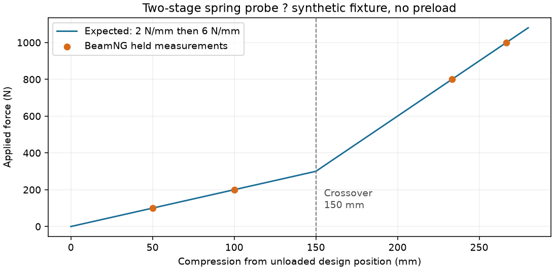
This retained native test output shows a two-stage spring rather than the single-rate illustration above. See Coilovers for the measured rates and the limits of this evidence; this recording does not qualify a complete vehicle.
Pressure wheels
Section titled “Pressure wheels”BeamNG pressure wheels supply hub/tread nodes, pressure groups, tire beams and contact. The verifier inspects the compiled wheel topology and effective collision flags.
The cad_axisymmetric mass option fits CAD total mass and axial inertia, with a reported approximation to transverse inertia. It uses the declared bearing axis and CAD COM rather than assuming a bearing-face datum is the tire centre. Infeasible positive mass/radius allocations are rejected.
Tire damping, precompression, bead width and hub stiffness are physical model settings that require a new verified package when changed. Native wheel-axis measurements help distinguish carrier alignment error from carcass deformation.
Torque paths
Section titled “Torque paths”The supported geared-AWD layout is:
Engine → centrifugal clutch → CVT → rear reduction → carrier takeoff ├→ rear differential → rear wheels └→ front output gearing → front differential → front wheelsThe front output is upstream of the rear left/right differential, not taken from a rear halfshaft. The RWD layout omits the front driven branch.
Reaction nodes bind the engine and differential devices to their physical housings. Braking reacts through uprights or trailing arms. The numerical torsional budget includes both geared wheel inertia and housing recoil; provisional coupling compliance does not calibrate real shaft twist, heating or failure.
Native verification checks device parents, ports, ratios, wheel directions and reaction bindings. Supported tests also reject repeated wheel-speed reversals that an average-speed check could conceal.
Collision boundary
Section titled “Collision boundary”The wrapped frame is an external envelope spanning gaps between tubes. In a full vehicle it retains terrain/other-vehicle collision while disabling internal self-collision, avoiding false contact with attached parts inside that envelope. Contact with the actual individual frame members requires a different representation.
Read Verification before treating a generated vehicle as accepted.