Author joints and fasteners
Implementation snapshot · 2026-10-12 · Sources & update notes
The importer follows reference planes, axes, points and sketch dependencies to their tagged CAD owners. Assembly mate folders are excluded from that dependency walk. Fully constrained assembly datum sketches with no component dependency can use the unique fixed frame as assembly ground; ambiguous or untagged dependencies remain explicit importer errors. A solved SolidWorks mate and a supported BeamNG joint are separate checks: an importer error does not mean you must redo the CAD mate.
For a rear arm with one chassis ball joint, two radius rods attached to the arm, a hinged upright and a separate toe link, choose Ball-pivot trailing arm + 2 radius rods + hinged upright + toe link. This is separate from the existing two-pivot arm / ball-carrier option. The carrier hinge uses two points from the native reference axis, shared by arm and upright; these are constraint sites, not inferred bearing locations. Both radius rods retain spherical ends on the arm, and the toe rod retains spherical ends on the upright. The generator, spring-load calculation and motion comparison use this same topology.
Auto-inferred hardpoints refresh when native joint geometry changes; manually captured points remain user-owned. The current CAD regression recovered all 50 required suspension points and checked one DOF with ±30 mm analytical travel at each corner. This is not a live BeamNG qualification or a hardware travel limit.
Preview automatic connections
Section titled “Preview automatic connections”Quick first pass: Joints & mounts → Auto-connect. This scans the current companion’s mates and fixed placements, exports current tagged geometry, and opens a searchable preview. It does not apply proposed connections until you choose Apply checked proposals. Select a row to highlight its component and display proposed bolt sites/support lines in the assembly. Only ready rows can be applied. The preview lists missing support, ambiguous geometry, unsupported joint motion, missing shaft endpoints, and fixed parts assigned moving roles.
For panels, the wizard traces the outer projected mesh boundary, ignores holes, insets the corner sites (default 10 mm), and searches along each local inward normal toward the frame centre. It chooses the nearest fixed structural support within the search distance (default 50 mm). Overlapping supports, ambiguous boundaries, or corners with no support require manual review. The Reverse auto-bolt normal setting lets you reverse the search direction for a group. The preview records the support contact separately from the short attachment: parent-owned structure reaches the panel site, while the detachable connection uses the existing short-connector representation. This is provisional attachment geometry, not a reconstruction of the actual bolt or bracket hardware.
Panel bolts default to independent failure, a 6 mm connector length, and 4000 N strength per connector beam. These are starting values, not calibrated bolt ratings. Fixed non-moving groups receive permanent rigid attachments to the frame. A fixed suspension/wheel/shaft role is flagged instead of welded in place. Native joint inference matches component roles and connected owners; it retains distinct native pivot locations and does not invent hardpoints from mesh bounds. Axes without sufficient endpoint information, intermediate shaft carriers, and ambiguous assembly references still need explicit CAD point capture/review.
Applied fasteners remain editable in Panel / accessory fasteners. Add real bolt sites there whenever available; the wizard does not replace that workflow. Regeneration preserves manual and edited connections. Before applying proposals, the wizard saves a project backup beside its report and shows the backup path. Changed geometry invalidates generated mounting references until reviewed again. The vehicle build checks the frame geometry, project identity and mount plan; an outdated frame is prepared for fresh calibration, with the existing fixture review before calibration proceeds. Completing inference is not BeamNG qualification.
Choose representation and mass ownership
Section titled “Choose representation and mass ownership”Representation and mass are separate settings in the component properties:
| Representation | Mass setting | Exported behavior |
|---|---|---|
| Physical | CAD or custom positive mass | Own nodes, collision and supported mounting behavior |
| Visual only | CAD or custom positive mass | Mesh follows a physical parent; mass, COM and inertia are fitted into that parent’s nodes |
| Visual only | Exclude mass | Mesh follows its parent with no mass contribution; explicit acknowledgement required |
Visual-only parts have no independent collision, fasteners or breakaway. Choose a parent, and a specific moving member when the parent is split. Zero mass is never silently accepted as a physical part: provide mass or select Visual only and use Accept visual only with excluded mass. The acknowledgement covers the geometry and mass settings and must be repeated when they change. The component list continues to show the visual-only/excluded-mass state after acknowledgement. Positive visual mass is transferred exactly once using the parallel-axis theorem; the original component assignments stay intact. For an existing calibrated frame, the added visual mass is fitted separately and added to its existing node masses. No original frame node loses mass, and its springs remain unchanged. A host whose node graph cannot fit the added mass, centre of mass and inertia is rejected. Visual-only groups are omitted from physical mount generation; an unknown mount owner is still an error. Endpoint-only wheel, shaft, locating-rod and coilover models currently require a rigid host for positive visual mass rather than silently dropping its inertia.
Capture actual fastener sites
Section titled “Capture actual fastener sites”For a first mounting pass, start with one panel. Keep the frame fixed and mate the panel into its installed position in the current companion assembly. At each actual bolt site, save a point on the frame and a matching point on the panel using CAD reference points → Add from CAD selection. A circular hole edge provides its centre; a sketch point can represent a site without modelled holes. Then use Panel / accessory fasteners to connect the frame point (From) to the panel point (To). Repeat for the separated attachment sites. Saving a reference point alone does not attach the part.
Choose Breakable attachment for detachable mounts. An empty Release together set lets each connector fail independently; a shared set on one part releases its connectors together. Failure force is per generated connector beam, not a calibrated bolt rating. Engine/accessory mounts use the same attachment workflow; their stiffness and damping need to represent the actual mounting hardware. Suspension ball joints, hinges and sliding members instead use the native-mate review and hardpoint binding steps below, so their intended motion remains free. You do not need to draw BeamNG nodes manually.
Review native joints and build the definition
Section titled “Review native joints and build the definition”- Create/open the current working CAD assembly, save it, and select Authored CAD joints in Joints & mounts. Keep the frame fixed. Native Mate command opens SolidWorks’ Mate tool for geometry selected on two tagged companion instances; it floats the selected non-frame instances. The searchable list combines required hardpoints, mate proposals and mounts.
- A group containing independently moving bodies must be split first. Select the group, open Components → CAD assignment → Moving pieces / split for mates (also available on Coilover), and classify every physical body exactly once using the moving-piece dropdown. Clicking a row highlights its body in the assembly without moving the camera; Ctrl/Shift selects several. Choose a piece and Assign to selected bodies to classify them together. Zoom to selected bodies explicitly moves the camera. Then save, and create its companion revision. New companions automatically split complete coilover housing/shaft/spring assignments into separately mateable instances. Existing combined companions still use Create moving companion revision. If that dialog contains blank rows, some physical bodies were not included in the saved piece assignments: click those rows to identify them and complete their classification. Steering needs a housing and a rack; coilovers can use housing, shaft and spring. The logical CAD group stays intact while each member becomes a separately mateable native part. This creates a new revision and keeps the previous assembly. Reopening and refreshing source geometry preserve member ownership; changed body partitions require explicit source classification. Repair affected references.
- Use native mates to describe motion, then Scan native mates. A solved point coincidence becomes a spherical proposal; concentric axes permit spin and slide; an axial stop removes slide; concentric axes with locked rotation permit slide. Combined constraints determine the result. Inspect each proposal and Approve joint. Use Positioning only for a constraint deliberately excluded from physics. Unsupported/unsolved/stale constraints block generation.
- Select each requested hardpoint and Capture selected CAD point, then Bind reviewed joint. Keep the captured point for the two hinge pivots or wheel-bearing endpoints; both must lie on the reviewed axis. You can also bind directly to a joint centre without capturing a separate point. Off-axis points and stale joint approvals block generation. Highlight CAD selects the saved native geometry. The skeleton shows what is requested; its example coordinates are never assigned to your car. Changes to native mates trigger review again, including at build time.
- For each panel/accessory fastener, capture matching parent and child points. Under Panel / accessory fasteners, set From to the parent and To to the panel/accessory. Add separated sites (at least three non-collinear sites for a rigidly mounted part). Choose Breakable attachment, a per-beam failure force and the short connector length. Leave Release together set empty for independent bolts/clips; use the same name on one panel only when those mounts should release together. Another panel with that name remains separate. A reviewed rigid native panel placement is satisfied by these mounts; no extra permanent weld is added. A ball/hinge placement cannot silently become a rigid fastener pattern.
- Review Physical parameters: rack half travel is metres from centre to an
end stop. The candidate’s
rack_speed_m_sis the maximum commanded travel speed (default 0.1 m/s); set it to match the steering hardware. This controls the generated actuator, including during verification. Wheel dimensions, pressure and drivetrain values must match the hardware. Multi-section shafts use separately tagged sections, supported endpoint joints and carrier groups. Their order is derived from those joints, including changes of axis. Setshaft.<component ID>.plunge_mexplicitly when a slip joint is required; zero is a fixed-length section. - Check definition, refresh/export CAD, then regenerate/calibrate the frame with the resulting mounting plan before packaging the full vehicle. Changing fastener position or short-link length invalidates that plan. Verify packaged attachments runs the mounting/release suite separately from driving acceptance. It keeps separate mounting and driving qualification statuses.
The short-link length control applies to breakable frame mounts and connections between other parts in authored full-vehicle generation. Permanent frame mounts use the existing structural supports; they do not add a small breakaway cage or consume additional frame nodes. Changing an attachment between permanent and breakable requires a fresh frame calibration. Legacy component-only packages keep their existing attachment representation; switching a project to authored mode is explicit.
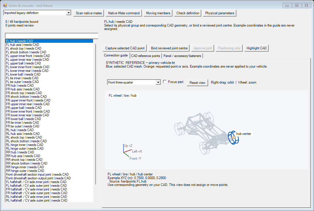
Annotated native evidence and release diagram (local source: docs/joints-and-mounts.html)
shows the independent-fastener stages and the rack sweep. These are controlled
synthetic fixtures, not measured bolt strengths or real-car acceptance.