Use the reference skeleton
Implementation snapshot · 2026-10-12 · Sources & update notes
FL/FR and RL/RR mean front/rear vehicle left/right while seated facing forward. BeamNG defines left as +X, forward as −Y and up as +Z (coordinate reference). The front view therefore shows vehicle left on the screen’s right. Choose Rear (looking forward) for left-on-left, or Top (forward up) for a plan view. The front three-quarter view looks down from above; changing view never swaps role names or assignments.
Open Components / mounts → Joints & mounts → Connection guide, or use Locate on reference skeleton beside the CAD assignment’s role picker. The searchable request list includes the applied configuration’s hardpoints and their assignment/review status. Selecting a request shows its labelled example point. Browsing the reference does not change the assignment.
- Select a part to highlight its visible CAD mesh in blue on the test car.
- Select a hardpoint request to show its orange marker and label. Wheel axes use two declared points. Separate housing/panel mounts appear as separate points. The guide is illustrative; capture the corresponding point on your CAD.
- Right-drag to orbit, use the mouse wheel to zoom, or choose Top, Front or Side. Focus part frames a small component; Reset view restores the whole vehicle. Coordinates use BeamNG metres: +X left, -Y front, +Z up.
- The guide matches the primary trailing-arm/AWD, alternate rear-wishbone/RWD, or optional trailing-arm/radius-rod/toe-link AWD configuration. The latter has three focused native tests; older archived configurations also have driving-test evidence. Those results apply only to their recorded builds. Other combinations explicitly show no tested reference. Some requests, such as the engine bearing axis or a separate caliper mount, were not geometrically declared in the synthetic MVP. They say not located rather than receiving invented coordinates. They still need your CAD input.
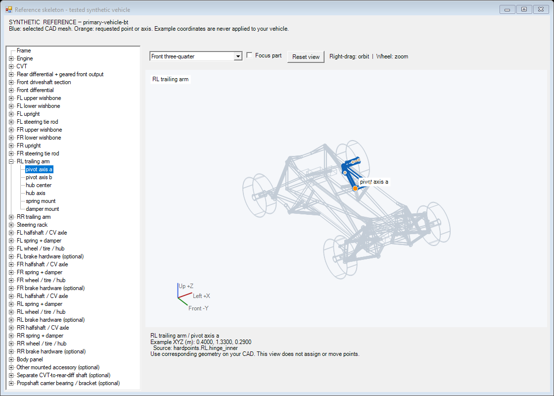
This is a read-only synthetic reference, not a view of your generated vehicle or a hardpoint assignment tool. Markers describe attachment definitions, not every generated simulation node. It loads local illustration assets without launching BeamNG, Python or another SolidWorks document.
The component window separates CAD assignment, Appearance, Physical properties, and Hull preview under Components. Build / test groups the export, generation and verification steps; Log has its own page. Task progress and Stop task appear only while an operation is running.