Coilovers and spring settings
Implementation snapshot · 2026-10-12 · Sources & update notes
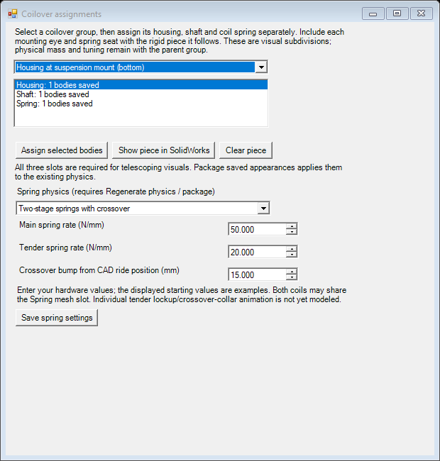
Select a *_spring_damper group in Components, then open Coilover.
Assign the housing (including its eye and spring seat), shaft (including its eye
and seat), and coil spring into the three slots. Each slot accepts multiple
bodies, shows its saved body count, and can highlight its selection in SolidWorks.
Choose whether the housing attaches to the chassis/top mount or suspension/bottom
mount. Complete all slots, then use Package saved appearances on Appearance
or Build / test. The split also applies when regenerating full-vehicle physics.
Selections survive restarts; partial or overlapping assignments block packaging
without discarding saved work. Existing combined assignments stay usable until
you opt into split visuals. Clear every slot to return to a combined mesh.
Housing and shaft export as rigid native props anchored at opposite shock eyes. Each uses the other eye for its longitudinal axis and an existing, non-collinear suspension node for roll. The exporter moves mesh vertices relative to their mounting eye and preserves the authored rest orientation. Changing eye distance therefore telescopes the pieces without stretching their metal bodies. Only the coil uses the existing suspension flexbody binding. This follows BeamNG’s recommended mesh separation. Captured appearance slots are retained for all three pieces.
Splitting visuals adds no nodes, mass or forces. The parent physical group still supplies coilover mass, and the existing bounded beams supply spring preload, damping and travel limits. Appearance packaging checks that the physical snapshot is unchanged. It does not infer measured spring/damper specifications from CAD. The coil is a deforming render mesh, not an individually simulated helical wire; large crash deformation and spring-seat detail still need visual review.
The native articulation harness captures each split coilover at rest and bump and checks that all rigid props and spring flexbodies loaded. The independent fixture includes an inverted front-right shock and retains the accepted vehicle’s physical snapshot. These checks cover motion and rendering, not real shock ratings.
Optional two-stage springs
Section titled “Optional two-stage springs”In the same Coilover tab, choose Two-stage springs with crossover for each corner that needs it. Enter the main and tender spring rates in N/mm and the shock compression, in mm from the CAD ride position, where the crossover engages. Click Save spring settings, then Regenerate physics / package. Appearance-only packaging keeps the previous physics. The default remains the automatic single-rate spring; example values in the fields are not measured hardware specifications.
Before crossover, the two springs work in series:
k_initial = k_main * k_tender / (k_main + k_tender). After crossover, the main
spring determines the rate. The generator retains automatic static preload and
adds a parallel compression-only support beam
with stiffness k_main - k_initial and rest length equal to the shock length at
crossover. It is unloaded until crossover, then supplies
(k_main - k_initial) * (compression - crossover): force stays continuous while
the rate changes. This leaves the existing travel stops independent of crossover
and adds no node mass. Damping is recalculated from the
initial spring rate; this option does not implement two-stage damping.
Both coil meshes may be assigned to the Spring slot, but individual tender spring lockup and crossover-collar animation are not implemented. Housing and shaft still telescope as rigid pieces. The settings describe spring force versus travel; they do not infer rates, preload or crossover position from coil geometry.
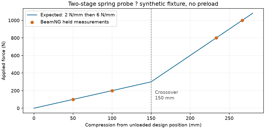
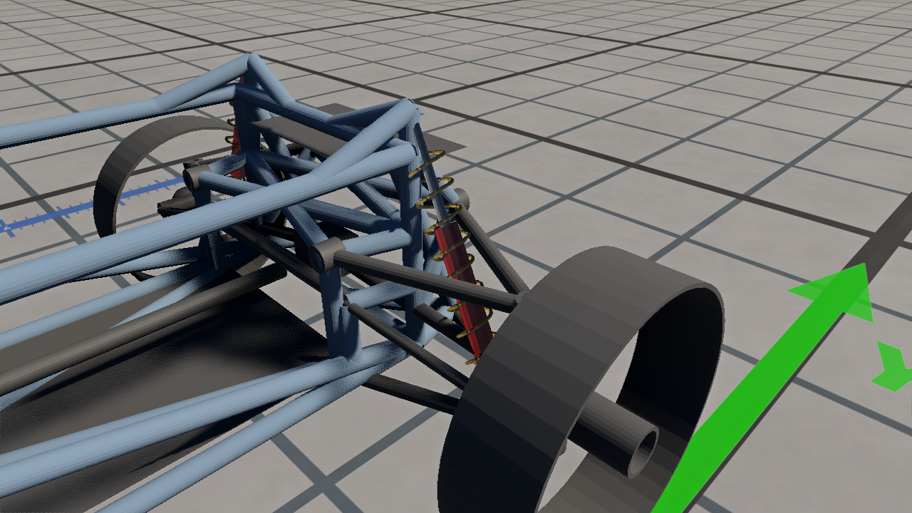
The native scalar fixture measured 2,000.7 N/m before crossover and 6,007.6 N/m after, against targets of 2,000 and 6,000 N/m. All four recordings passed the position/velocity, settled-hold and intact-structure checks; their held positions were within 1% of the expected continuous force curve. A fresh vehicle build with the option on one corner also passed articulation. The inverted shock below has a red housing, silver shaft and yellow coil. These are synthetic test meshes.
Reproduction helpers: tools/verify-dual-rate-spring.py,
tools/verify-coilover-visuals.py, tools/Test-CoiloverAssignments.ps1 and
tools/Test-CurrentGeometrySelection.ps1. Detailed recordings remain in the local experiment archive.
Imported steering-rack surface features can be assigned directly. A selected
RefSurface is expanded through its faces to its owning surface bodies only.
Unrelated edges/features still require an explicit whole-component action.
Surface mass still requires thickness/material or the existing weightless option;
accepting a selection does not turn a sheet into a solid.