Alpha wrapping and frame graph generation
Implementation snapshot · 2026-10-12 · Sources & update notes
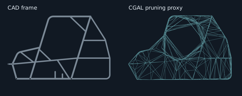
A tube frame has many openings. To build an outer shell, the generator first needs a closed volume that distinguishes outside space from the space enclosed by the frame. CGAL alpha wrapping supplies that pruning proxy.
α = frame diagonal / divisor · offset = α / ratio
Load the 3D view to orbit the frame and compare computed stages.
The proxy closes gaps for inside/outside classification. Its vertices do not become the final frame nodes.
What is computed here?
Each setting selects an actual CGAL and Blender run on the same CAD export. There are nine sampled combinations, with no interpolation. The browser renders the saved outputs; CGAL is not running in your browser.
Held fixed: grid 3 × 5 × 7, projection offset 10 mm, weld distance 150 mm, symmetry off. These are example settings, not recommended defaults.
Source: 43,963 triangles, metres. The extracted model and each computed result are fingerprinted in the dataset manifest.
What alpha and offset change
Section titled “What alpha and offset change”Alpha controls which openings the wrap can enter. A larger alpha spans more small gaps; a smaller alpha follows more detail. The add-in exposes a divisor: alpha = frame bounding-box diagonal / ProxyDivisor. Increasing the divisor therefore decreases alpha.
Offset keeps the wrap away from the source surface. Here offset = alpha / ProxyOffsetRatio. Increasing that ratio brings the proxy closer to the CAD and usually increases its triangle count. Changing the alpha divisor also changes the absolute offset unless you compensate with the ratio.
CGAL starts with an enclosing Delaunay triangulation and traverses from the outside. It removes eligible tetrahedra while respecting the input and offset surface, refining where needed. The remaining boundary is a closed triangular envelope. The explorer shows the exact resulting envelope; it does not invent an animation of CGAL’s internal traversal. See CGAL’s algorithm description.
From proxy to hull
Section titled “From proxy to hull”- Classify grid cells. Mark cells that intersect the proxy. Flood-fill empty cells from the outside. Keep the intersecting cells and enclosed empty cells.
- Extract the boundary. Faces between retained and removed cells form a coarse surface. Grid dimensions determine its available vertices.
- Project to the original frame. Blender moves those vertices to the original CAD triangles, with the requested projection offset. This is a separate offset from CGAL’s proxy offset.
- Apply symmetry and weld. Symmetry, when enabled, mirrors one source half. Welding combines nearby projected vertices. Inspect small corners and thin faces after changing either setting.
The proxy’s triangle count is not the final node count. Compare CGAL proxy and Weld while changing the offset ratio: a denser proxy can still produce almost the same coarse hull.
From hull to graph
Section titled “From hull to graph”The shell generator triangulates the hull, puts nodes at its vertices, and adds beams along the surface edges. It then constructs an internal cage and attaches shell nodes to it. In Structural graph, blue marks shell connections and orange marks internal supports.
The generator checks the rigidity matrix for extra internal motions. A free three-dimensional rigid graph has six whole-body motions and rank 3N − 6. Passing that check establishes geometric rigidity, not the correct material response.
Local bracing adds tetrahedral and nearest-node connections before fitting. Mounting supports must also be inserted before calibration. The selected model has no vehicle mounting patches, so those are not shown in this dataset.
Continue to Frame calibration to see how masses and spring coefficients are fitted while holding this graph fixed.